




Table Of Content
A practical reference implementation for integrating TFT displays, DMA-driven rendering, PSRAM framebuffers, and LVGL on Silicon Labs wireless microcontrollers.
Introduction to SiWx917 for Embedded IoT Interfaces
Bringing a graphical interface to a wireless IoT device requires more than connecting a display. The firmware must coordinate communication peripherals, memory allocation, display commands, and rendering updates within the limits of an embedded system. The Silicon Labs SiWx917 provides a practical foundation for this type of work, combining wireless connectivity, embedded processing, and peripheral interfaces that can support sensors, displays, and other device components.
At Krasamo, we evaluated the SiWx917 as part of our work with Silicon Labs technologies and our broader embedded firmware and IoT development practice. This implementation documents a hands-on integration effort focused on understanding how the platform can support graphical interfaces for connected products.
Early connected device work often begins on rapid prototyping platforms used to validate interaction models, connectivity, and hardware behavior. The SiWx917 introduces a different set of considerations centered on tighter peripheral coordination, direct access to communication interfaces, and firmware environments that align more closely with production-oriented embedded systems.
For this evaluation, the BRD2605A development board is used as the hardware platform for working with the SiWx917, including access to onboard tools, sensors, and communication interfaces. The case study connects an ST7796S-based TFT (thin-film-transistor) display, brings up the display through GSPI (general serial protocol interface) and MIPI DBI (Display Bus Interface), uses DMA and PSRAM (pseudo static RAM) to support framebuffer transfers, and then integrates LVGL to move from low-level pixel rendering to a functional embedded graphical interface.
1. Development Environment Setup
Before integrating the display and graphics stack, the SiWx917 development environment must be configured with the required SDKs, tools, and project dependencies. This section covers the installation workflow used for the reference implementation.
Application development for the SiWx917 is primarily done using Simplicity Studio 6, the latest integrated development environment provided by Silicon Labs.
Installing Simplicity Studio 6
- Go to the official Silicon Labs website.
- Navigate to the development tools section and locate Simplicity Studio 6.
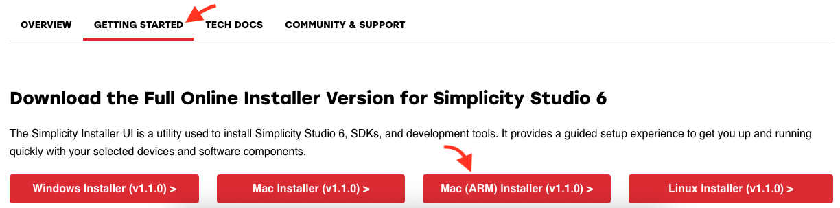
- Since I am using a Mac Mini M2 computer, I will select the version for macOS with ARM (Apple Silicon) architecture.
- Download the installer provided by Silicon Labs.
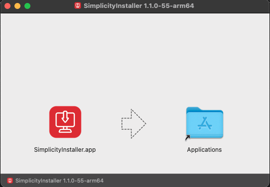
- Open the installer for Simplicity Installer.
- Open Simplicity Installer once the installation is complete.
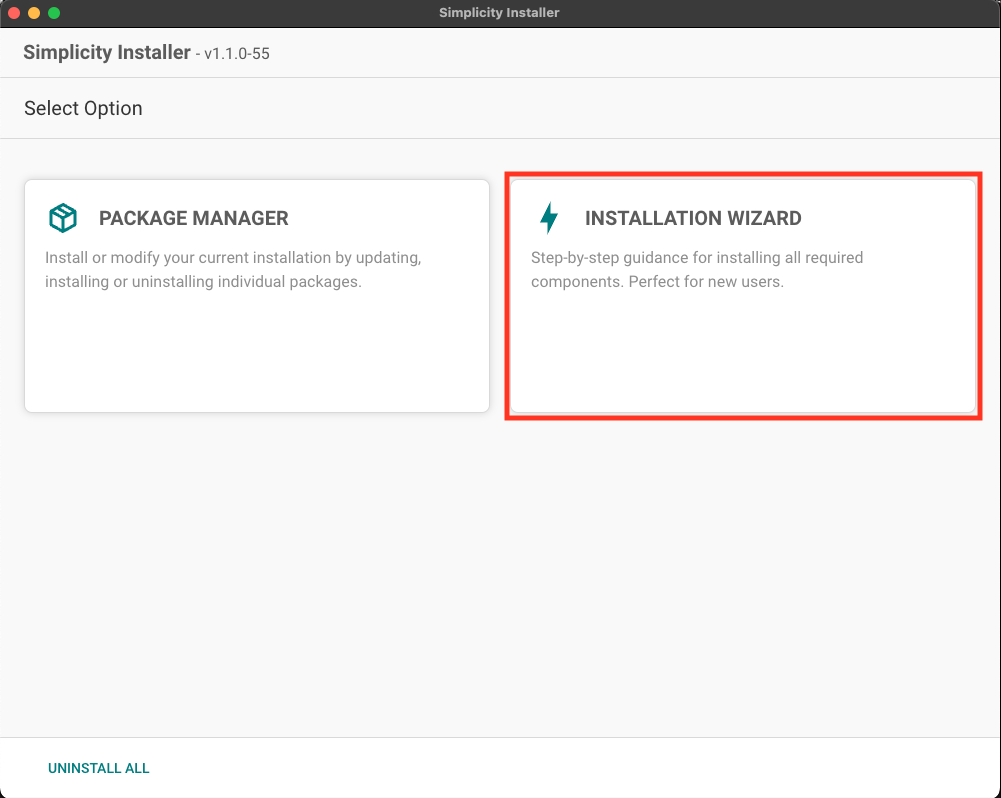
- Within Simplicity Installer, click on “INSTALLATION WIZARD”.
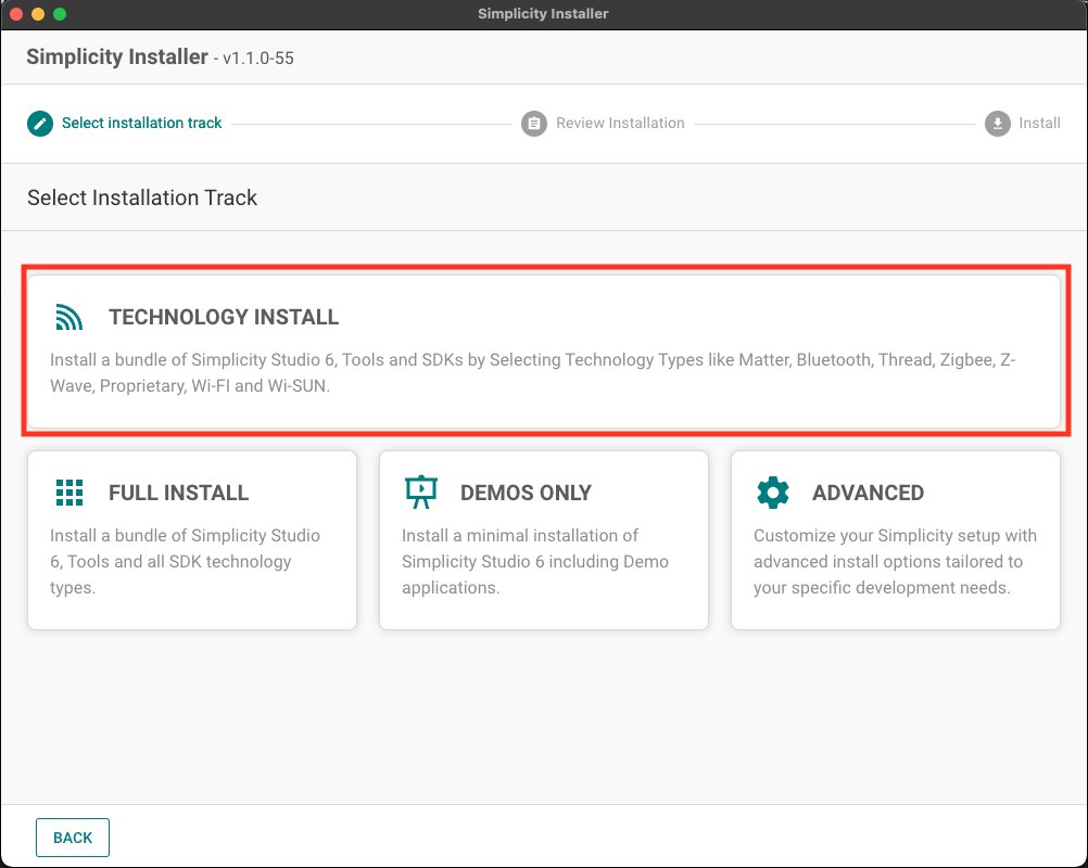
- Select “TECHNOLOGY INSTALL”. You can also select “FULL INSTALL” to install all SDKs and tools.
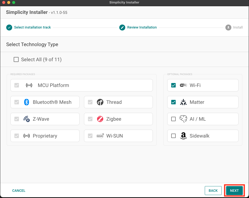
- Several additional technologies will be presented, but you are free to add others that are more convenient for you. Then click “NEXT”.
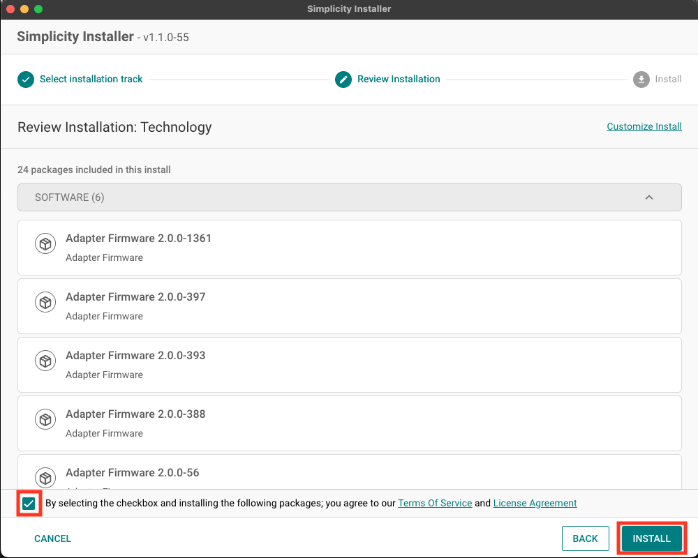
- Accept the terms and conditions and click “INSTALL”.
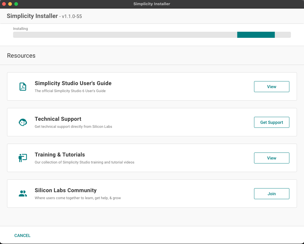
- Wait for the download and installation to finish.
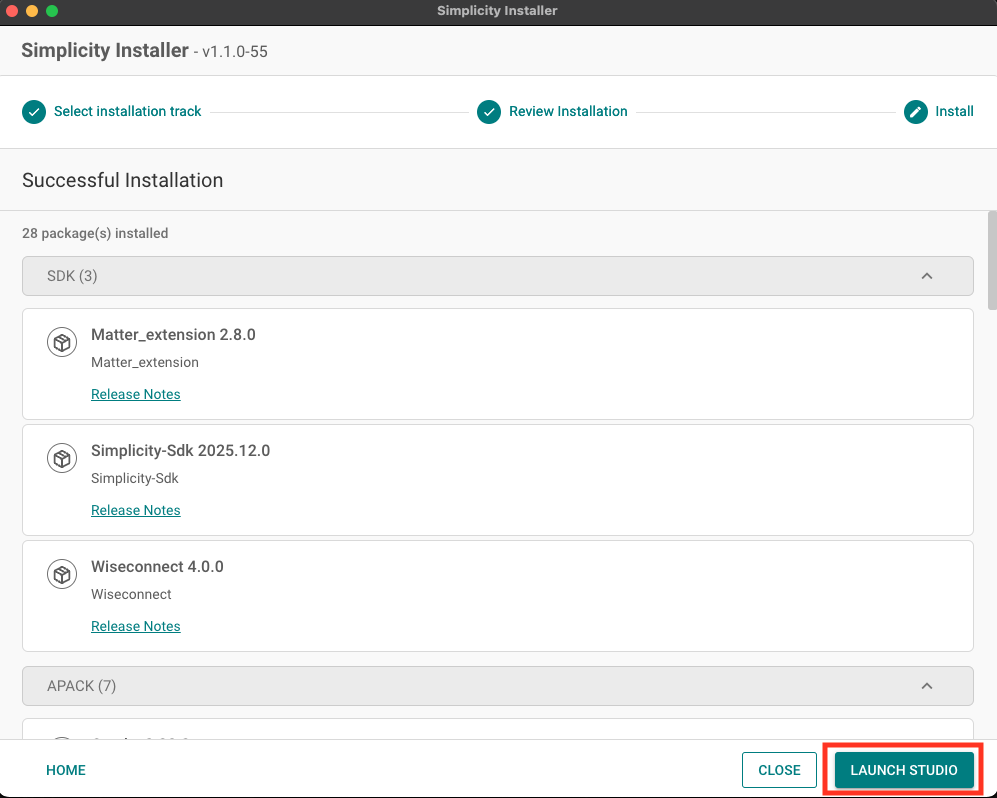
- Once the installation is complete, the button to open Simplicity Studio will appear, but we won’t explore Simplicity just yet. Let’s take a look at the VS Code extension.



Configuring the VS Code Extension
- Install Visual Studio Code from the official Microsoft website if it is not already installed.
- Access the extensions panel.
- Search for the Simplicity Studio for VS Code extension and select the official extension developed by Silicon Labs.
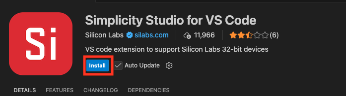
- Click the extension installation button.
- Restart VS Code if prompted by the system.
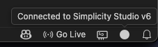
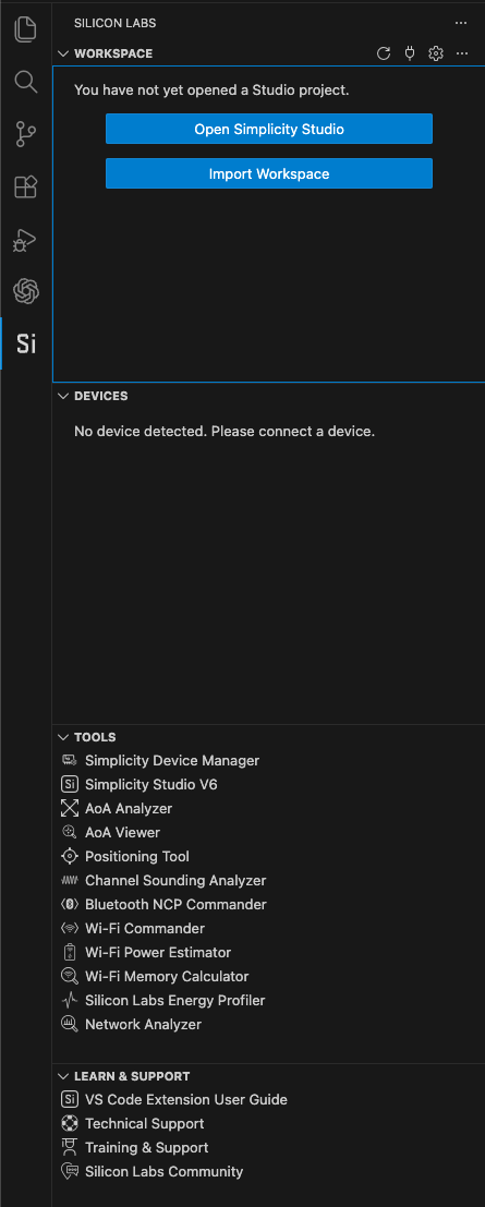
- Verify that the extension correctly detects the local installation of Simplicity Studio 6 by checking for a circle in the lower right corner.
- Confirm that the “Si” logo appears in the left sidebar and that the device, workspace, and tools panels are available within the extension panel.

Creating the Base SiWx917 Project
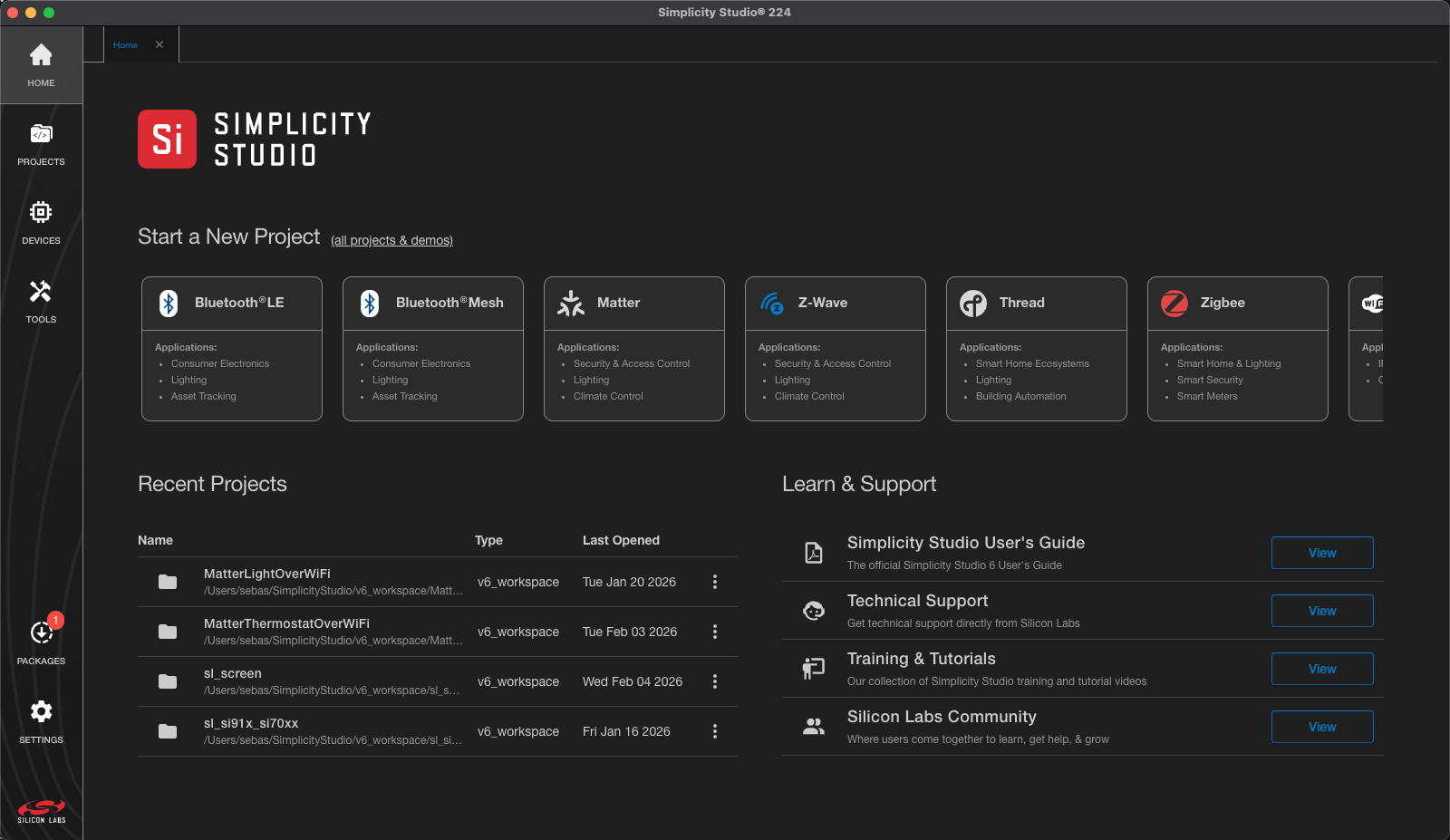
Let’s go back to Simplicity Studio. The left panel is where devices, settings, dependencies, projects, and configuration tools can be accessed.
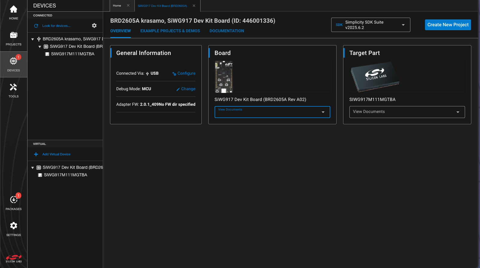
If we move to the Devices menu, the system automatically recognizes the connected development boards, allowing access to documentation, code examples, and hardware-specific configurations.
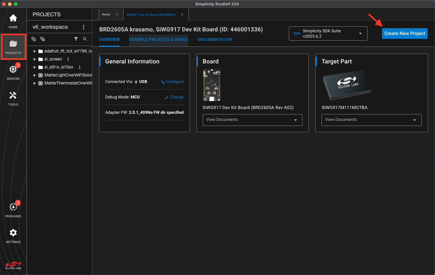
Now let’s move on to projects. All the project directories can be seen on the left and in the upper right corner, the button to create a new project.
The view will change to a search engine with several filters to select projects with examples or the code base for different purposes. In this case, we are going to look for an example using the GPIO peripheral. An important point is that the connected device will be displayed, which is important because it will filter out projects that are not compatible.
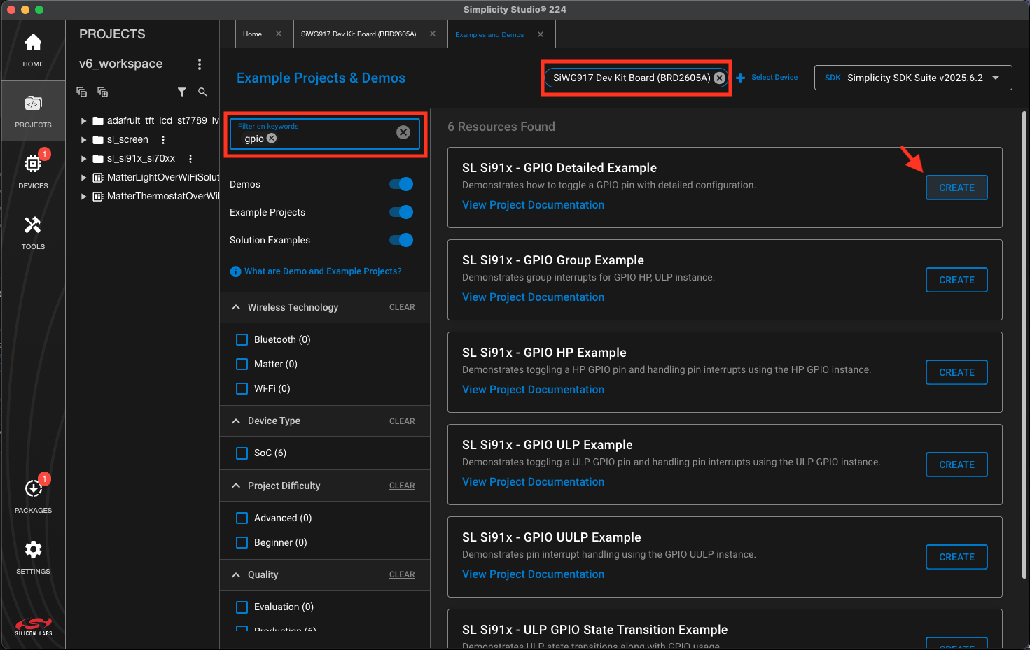
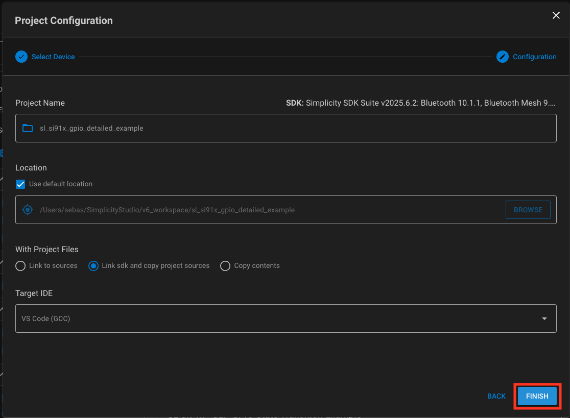
Pressing the Create button opens the project configuration dialog, where the project name, dependency handling, and IDE preferences can be adjusted. The default settings shown here are sufficient for the reference implementation.
Once the project is generated, click the Show button to open it in VS Code.
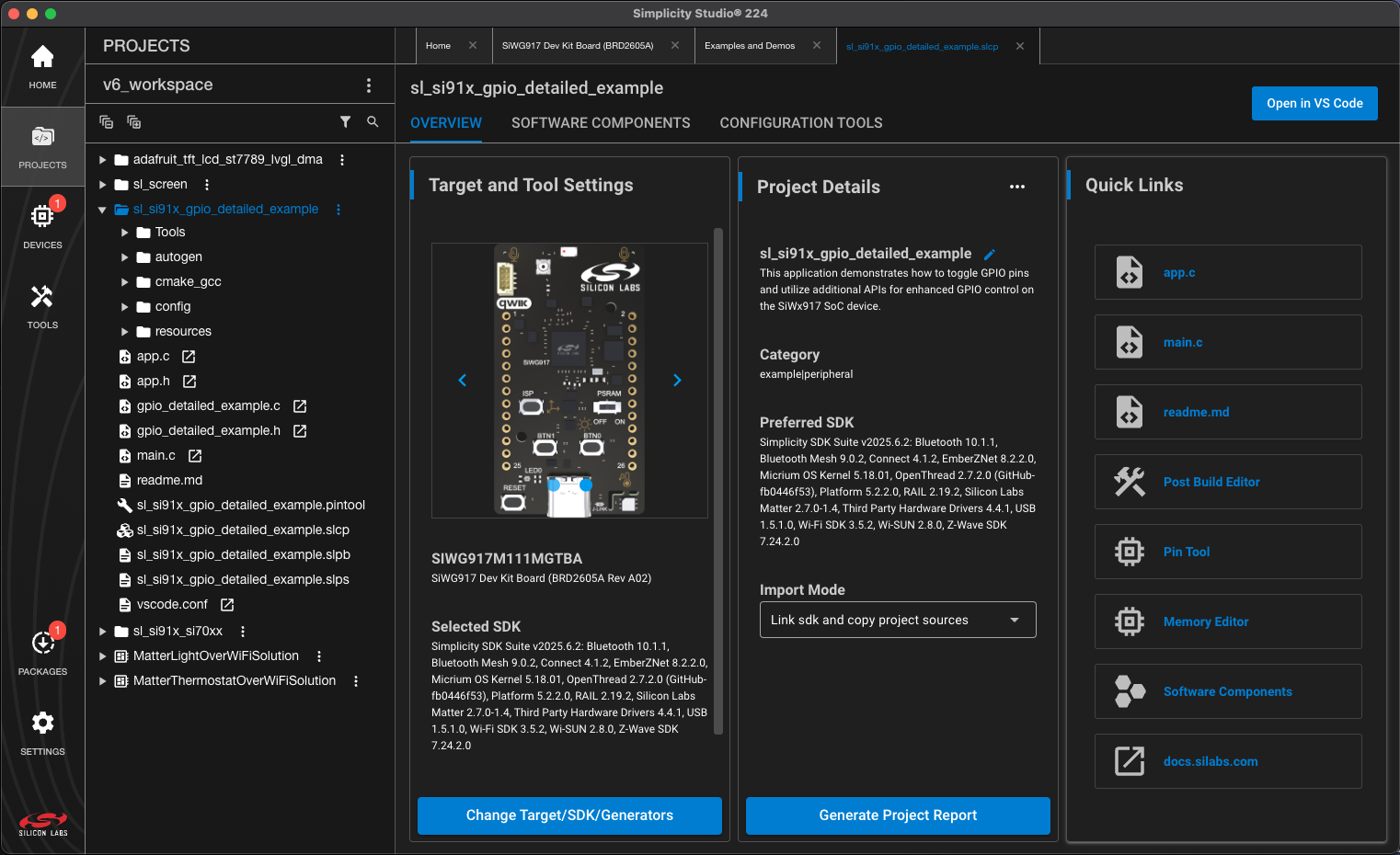
In VS Code, you should see something similar to the following image. The Simplicity extension panel is showing the project directories, tooling and the devices.
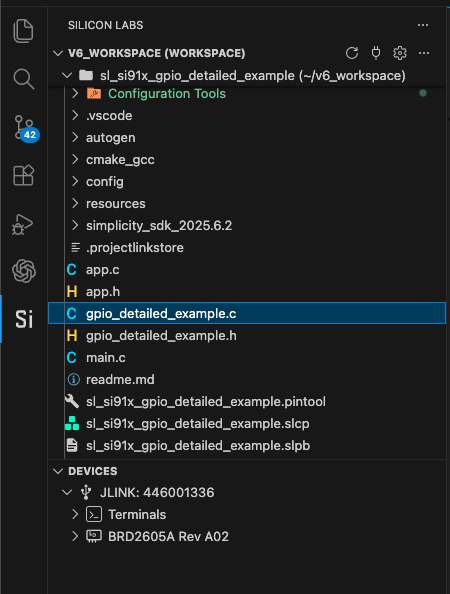
Understanding the Generated Project Structure
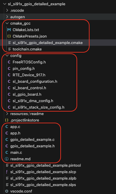
The project structure can be divided into three parts:
- The config folder contains the header files that are auto-generated with the values corresponding to the board and its components. In this case, we can see the configuration generated for RTOS, GPIO, etc. It is important not to modify these header files unless they have been generated incorrectly. The parameters are modified in the Software Components tab in the Simplicity project.
- The cmake_gcc folder contains the files related to cmake for compiling the project and linking it with all dependencies. There you will find the file project_name.cmake. Keep in mind that when a new component is added, the .cmake is refreshed.
- The code, main.c, app.c, and gpio_*.c, which initializes and manages the driver for the peripheral, are located in the root of the project.
Compiling and Flashing the Example Project
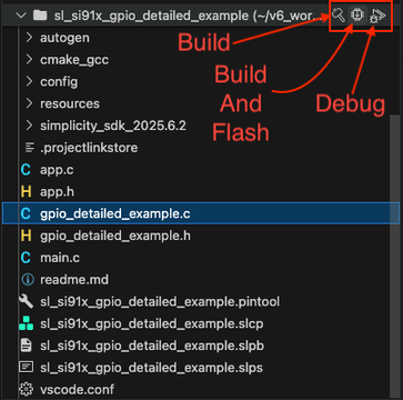
If you take a look at the code, you will see that it initializes GPIO pin number 10 and the direction is output. Next, the gpio_detailed_example_process_action function toggles the GPIO pin every 1s. You can connect an LED to the corresponding pin on the board and see how it turns on and off every second. The project can now be compiled and flashed to the board through the Simplicity extension panel. Hover over the project folder to display the available actions, then click the Flash button.
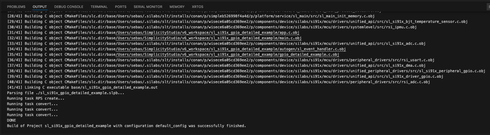
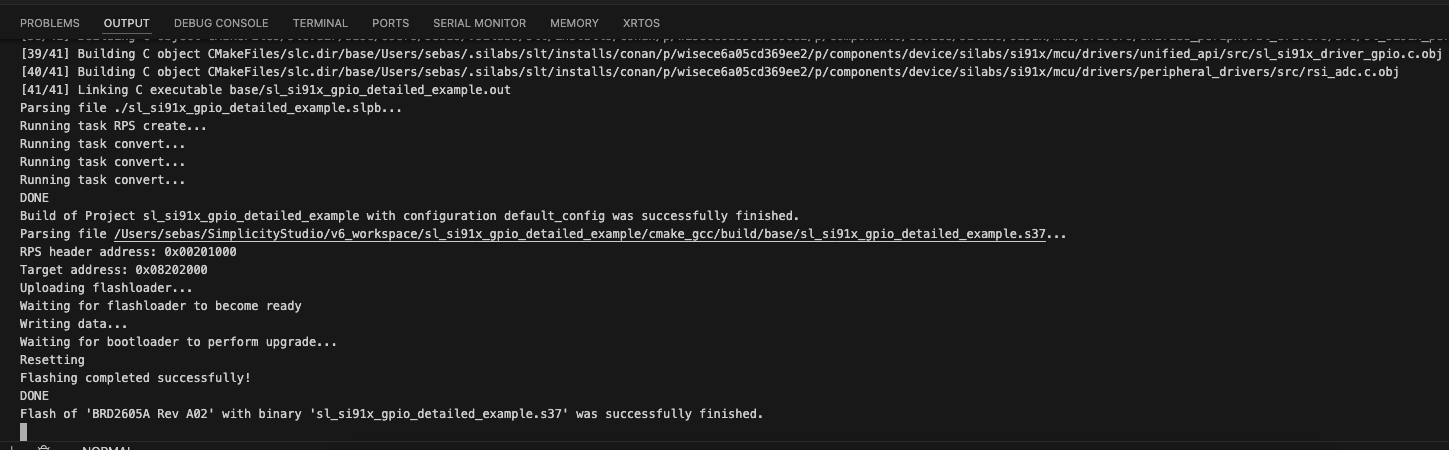
Next, a lower panel will open showing the terminal emulators. In this case, it will be the output tab, which will capture the STDOUT of the compilation and flashing. During compilation, we will see the cmake output.
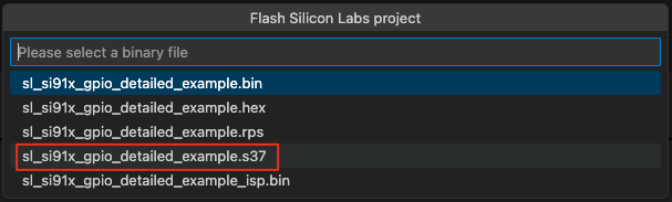
Once it finishes, a pop-out will open asking us which binary to flash. Select *.s37.
When the flashing is complete, we will see this in the output.
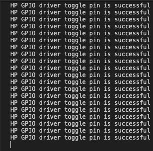
Now you should be able to see the LED blinking! In addition, using a program to read the serial port, you should see the logs.
WiseConnect SDK and Development Tooling
WiSeConnect is Silicon Labs connectivity software stack designed to simplify the development of wireless IoT applications using devices from the SiWx91x family. It provides a unified framework that integrates networking protocols, device management, security features, and hardware abstraction layers required to build connected embedded systems. In this example project, the GPIO driver was used to toggle pin 10.
Silicon Labs Docs AI
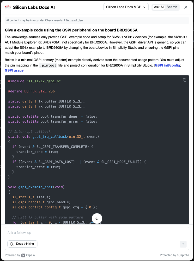
Silicon Labs also provides Silicon Labs Docs AI as an LLM-assisted interface for navigating the platform documentation. To start prompting, go to the docs page and click the search button.

2. Software Architecture for Display Integration
With the development environment configured and the base project running on the board, the next step is to add support for the ST7796S display. This requires selecting the display communication path, adding the necessary driver components, and preparing the project for graphics rendering.
Display support on this platform requires more explicit project configuration than selecting a ready-made library from the IDE. Silicon Labs provides the Third Party Hardware Drivers Extension repository, which includes drivers and sample projects for external components, with several examples that support the SiWx917 family.
One of the drivers we will need is MIPI Display Bus Interface. This driver allows us to communicate with the display through the GSPI (Generic Serial Peripheral Interface) peripheral, which is a primary-only SPI peripheral.
The next steps add the hardware driver extension, install the required components, and prepare the base project for the display implementation.
Install Third Party Hw Drivers Extension
The installation is quite simple. We begin with:
- Clone the repository.
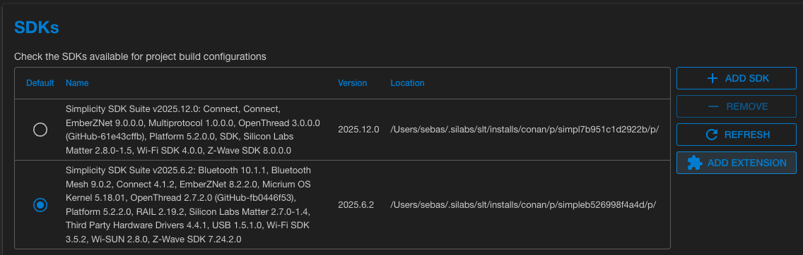
- Add the SDK in Simplicity Studio:
a. In Simplicity → go to the “settings” menu → select SDKs
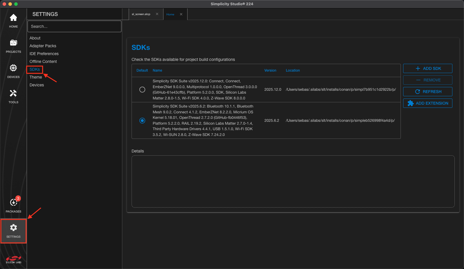

b. In the SDKs view → click “add extension” → click “browse” → select the repository folder from your filesystem and open it.
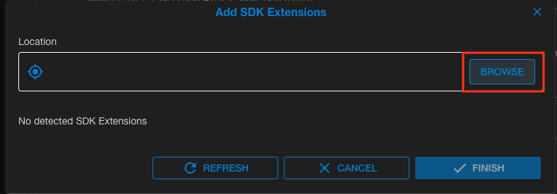

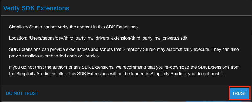
c. Check the SDK → click “Finish” → click “Trust.”
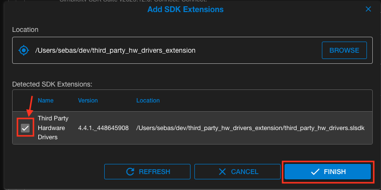
After the extension is added, return to the main SDKs view and verify that the Third Party Hardware Drivers extension appears under the selected SDK.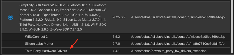
Include the MIPI driver
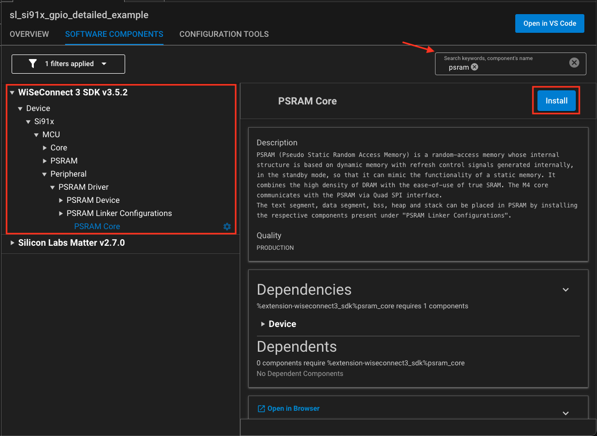
To include the driver, first install the GSPI and PSRAM software components (we won’t use this one yet). So, go to Simplicity in “projects” and select the project we generated as an example, then select “Software Components“.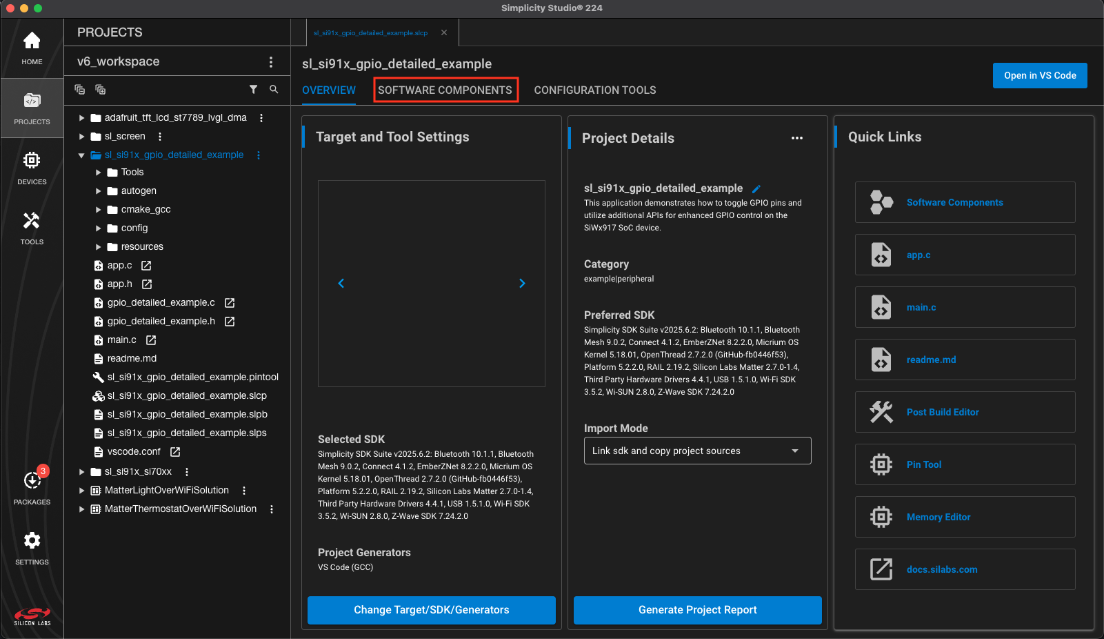 In the Software Components view, type GSPI in the search box. The component tree should filter the results. Then, expand the tree until you find the component, select it, and press Install.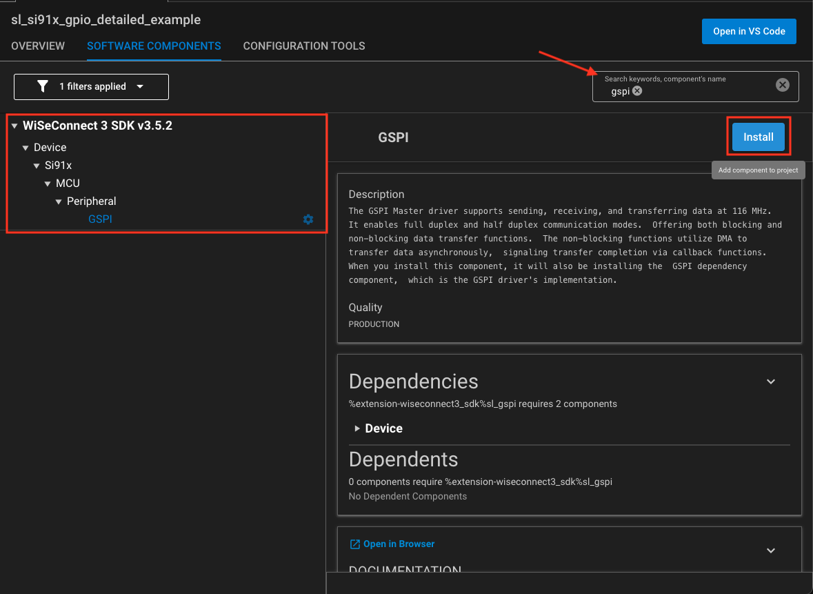
Once installed, we need to go to Configuration. There we can view the pins, bit rate, modes, and other configuration options; however, the most important thing is to activate the DMA (Direct Memory Access).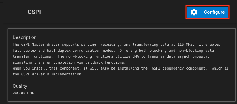
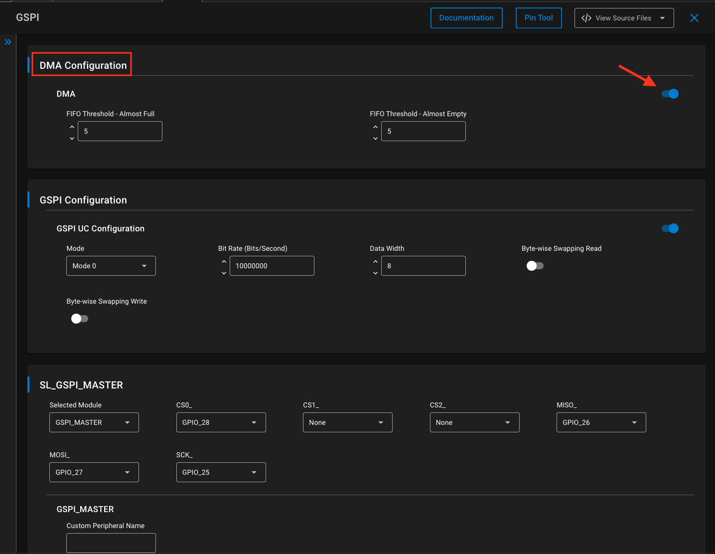
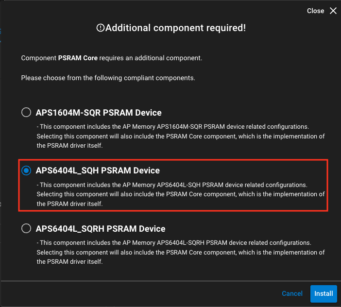
After making this configuration, you must search for the PSRAM component. This component is not required immediately, but it will later be used to allocate framebuffer memory for the graphical interface, since it installs the driver to manage the 8Mb of external pseudo-static memory that is available on the board. Installing the component opens a configuration dialog with three device options. Since you are using the BRD2605A board, you must select APS6404L_SQH.
Now we can install the MIPI component. This time, we need to activate some filters: check SDK Extensions and, in the Quality dropdown, select Evaluation. With this, type mipi in the search engine and the component should appear. But first, select “Third Party Hardware” and enable the extension.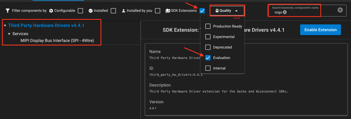
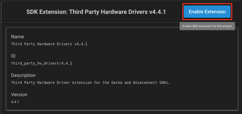
Once enabled, select the MIPI component and install it.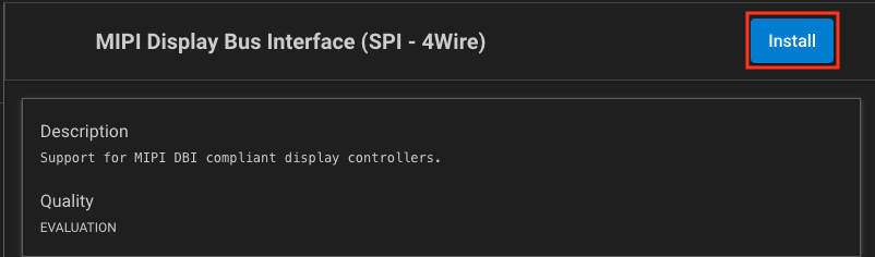
Once the components are installed, navigate to the project directory and open the config folder. You will see new files related to these components, confirming that the configuration was done correctly for the board.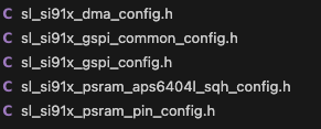
When the project is compiled at this stage, the build may fail because an additional dependency is still missing.
Another component needs to be installed, in this case the “Sleep Timer for Si91x“.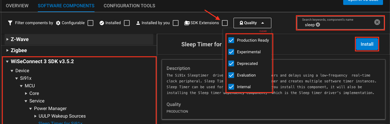
After adding the Sleep Timer for the Si91x component, the project compiles successfully.
Clean up the project
The base project being used has code that is no longer necessary for this demonstration, so the files gpio_detailed_example.c and gpio_detailed_example.h can be removed. And in the app.c file, we delete the references to the code we deleted.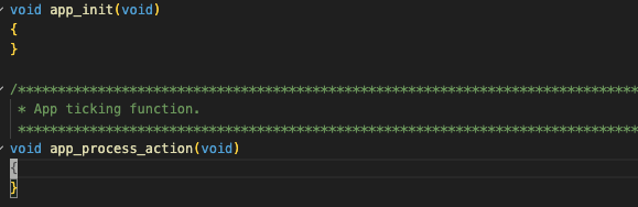
3. Physical connections
Before we start writing code, we need to connect the board to the display so we can see the results. The display operates at a logic voltage of 3.3V, and fortunately, the voltage from the board pins is also 3.3V, so there is no need to use a voltage divider. It also supports the SPI protocol for communication, both for the display itself and for reading the touch screen. Therefore, the connections would be as shown in the following diagrams.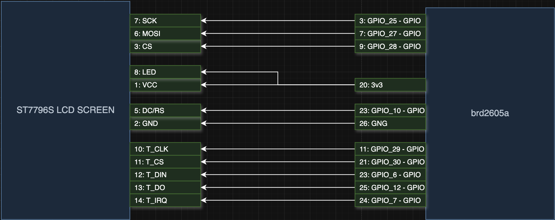
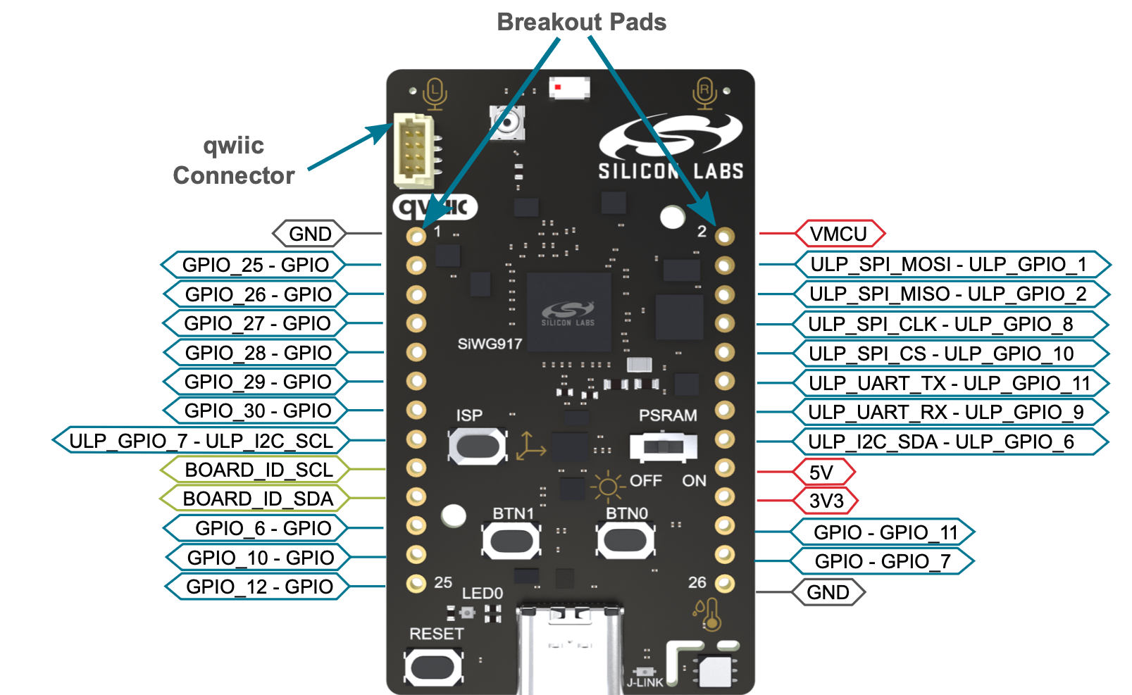
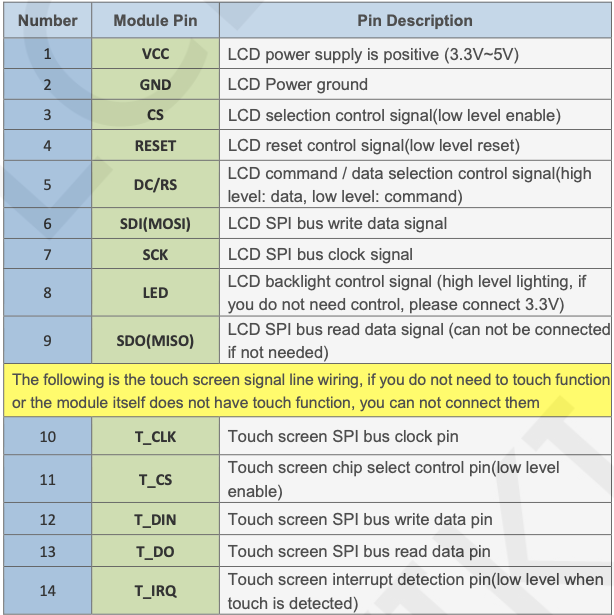
4. Rendering Graphics on Screen
With the hardware connections completed, the next step is to initialize the display controller and begin rendering pixel data.
#include "app.h"
#include <stdio.h>
#include <sl_status.h>
#include <sl_gpio_board.h>
#include <sl_sleeptimer.h>
#include <sl_si91x_gspi_common_config.h>
#include <mipi_dbi.h>
#include <mipi_dbi_spi.h>

#define BYTE_PER_PIXEL 2
#define MAX_FRAMEBUFFER_PIXEL_COUNT (MIPI_DBI_SPI_4WIRE_DMA_BUFFER_SIZE_MAX / BYTE_PER_PIXEL)
#define ST7796_SWRESET 0x01
#define ST7796_SLPOUT 0x11
#define ST7796_COLMOD 0x3A
#define ST7796_MADCTL 0x36
#define ST7796_INVOFF 0x20
#define ST7796_NORON 0x13
#define ST7796_DISPON 0x29
#define ST7796_MADCTL_MV 0x20
#define ST7796_MADCTL_RGB 0x00
#define ST7796_CASET 0x2A
#define ST7796_RASET 0x2B
#define ST7796_RAMWR 0x2C
#define ST7796_RAMRD 0x2E
#define DISPLAY_WIDTH 480
#define DISPLAY_HEIGHT 320
#define SL_GSPI_BITRATE 10000000

MIPI_DBI_SPI_INTERFACE_DEFINE(mipi_config,
  SL_GSPI_BITRATE,
  SL_GSPI_MODE_0,
  SL_GSPI_MASTER_HW_OUTPUT,
  SL_GSPI_MASTER_CS0__PORT,
  SL_GSPI_MASTER_CS0__PIN,
  HP,
  SL_SI91X_GPIO_10_PIN);

static struct mipi_dbi_device mipi_dbi_device;

sl_status_t send_command(uint8_t command, const uint8_t *dat a, uint8_t len);

void app_init(void)
{
   // init MIPI driver
   status = mipi_dbi_device_init(&mipi_dbi_device, (const stru ct mipi_dbi_config *)&mipi_config);
  if (status != SL_STATUS_OK)
  {
  	printf("mipi_dbi_device_init 0x%02lXrn", status);
  }
  // init ST7796 display
  status = send_command(ST7796_SWRESET, NULL, 0);
  if (status != SL_STATUS_OK)
  {
  	printf("send_command 0x%02lXrn", status);
  }
  sl_sleeptimer_delay_millisecond(150);
  send_command(ST7796_SLPOUT, NULL, 0);
  sl_sleeptimer_delay_millisecond(10);
  const uint8_t col_16bit = 0x55;
  send_command(ST7796_COLMOD, &col_16bit, 1);
  sl_sleeptimer_delay_millisecond(10);
  const uint8_t memCtrl = 0x55;
  send_command(ST7796_MADCTL, &memCtrl, 1);
  sl_sleeptimer_delay_millisecond(10);
  send_command(ST7796_INVOFF, NULL, 0);
  sl_sleeptimer_delay_millisecond(10);
  send_command(ST7796_NORON, NULL, 0);
  sl_sleeptimer_delay_millisecond(10);
  send_command(ST7796_DISPON, NULL, 0);
  sl_sleeptimer_delay_millisecond(10);
  // rotate 90deg
  uint8_t madctl = ST7796_MADCTL_MV | ST7796_MADCTL_RGB;
  send_command(ST7796_MADCTL, &madctl, 1);
  sl_sleeptimer_delay_millisecond(10);
}

sl_status_t send_command(uint8_t command, const uint8_t *dat a, uint8_t len)
{
  return mipi_dbi_device.api->command_write(&mipi_dbi_device, command, data, len);
}
First, the include of header files necessary for the project. Next, the declaration of the constants for the display command addresses. The MIPI driver is configured with the SPI peripheral information and the GPIO port that will be used to control the DC/RS pin. Finally, in the app_init function, the MIPI driver and the display are initialized using a specific sequence of commands.
An important detail is that the bitrate of the SPI peripheral is “hardcoded.” Although its value is already defined in the header file sl_si91x_gspi_config.h, it cannot be used because it causes conflicts with the macro MIPI_DBI_SPI_INTERFACE_DEFINE. Since it generates a variable with the name sl_gspi_control_config_t and the macro does too. Ideally, the bitrate constant defined in sl_si91x_gspi_config.h would be reused directly, because changes made through the GSPI component configuration would automatically propagate into the application code.
After the initialization sequence is implemented, the project can be compiled and flashed to the board. When you’re done flashing, the display should blink once and show unstable pixel data across the screen.
sl_status_t ST7796_set_addr_window(uint16_t x, uint16_t y, int16_t w, uint16_t h)
{
    sl_status_t status;
    uint16_t x1 = x + w - 1;
    uint16_t y1 = y + h - 1;
    uint8_t posx[4] = {x>>8, x & 0xFF, x1>>8, x1 & 0xff};
    uint8_t posy[4] = {y>>8, y & 0xFF, y1>>8, y1 & 0xff};

    status = send_command(ST7796_CASET, posx, 4);
    if (SL_STATUS_OK != status)
    {
        return status;
    }

    status = send_command(ST7796_RASET, posy, 4);
    if (SL_STATUS_OK != status)
    {
        return status;
    }

    // Write to RAM
    return send_command(ST7796_RAMWR, NULL, 0);
}
Transferring pixel data requires an intermediate DMA buffer because the MIPI driver expects a contiguous framebuffer region during GSPI transfers. The implementation separates this into two functions: write_display, which passes the prepared buffer to the MIPI driver, and write_color, which fills the DMA buffer with RGB565 pixel data before transfer.
// MIPI write_display expects a dma buffer
static uint16_t dma_buffer[MAX_FRAMEBUFFER_PIXEL_COUNT];

sl_status_t write_display(const void *framebuf, size_t framebuf_len, mipi_dbi_transfer_complete_callback_t callback)
{
    struct mipi_dbi_display_buffer_descriptor desc;

    desc.buf_size = framebuf_len;

    return mipi_dbi_device.api->write_display(
        &mipi_dbi_device,
        (const uint8_t *)framebuf,
        &desc,
        PIXEL_FORMAT_RGB_565,
        callback);
}

// len is the windows h*w
sl_status_t write_color(uint16_t color, uint32_t len)
{
    uint32_t i, n, size;
    sl_status_t status;

    if (!len)
    {
        return SL_STATUS_INVALID_PARAMETER;
    }

    for (n = 0; n < len; n += MAX_FRAMEBUFFER_PIXEL_COUNT)
    {
      // Calculated the number of pixels to flush into the DMA buffer
        if (n + MAX_FRAMEBUFFER_PIXEL_COUNT <= len)
        {
            size = MAX_FRAMEBUFFER_PIXEL_COUNT;
        }
        else
        {
            size = len - n;
        }
        printf("size %ldrn", size);

    // Fill the DMA buffer
        for (i = 0; i < size; i++)
        {
            dma_buffer[i] = color >> 8 | ((uint16_t)(color & 0xff) << 8);
        }

        status = write_display(dma_buffer,
                               size * 2,
                               NULL);
        if (SL_STATUS_OK != status)
        {
            goto error;
        }
    }

    return SL_STATUS_OK;
error:
    return SL_STATUS_IO;
}

void app_init(void)
{
  ...

    ST7796_set_addr_window(0, 0, DISPLAY_WIDTH, DISPLAY_HEIGHT);
    write_color(0xFFFF /*white color*/, (uint32_t)DISPLAY_WIDTH * DISPLAY_HEIGHT);
}
The result is a white background rendered directly through the display pipeline.
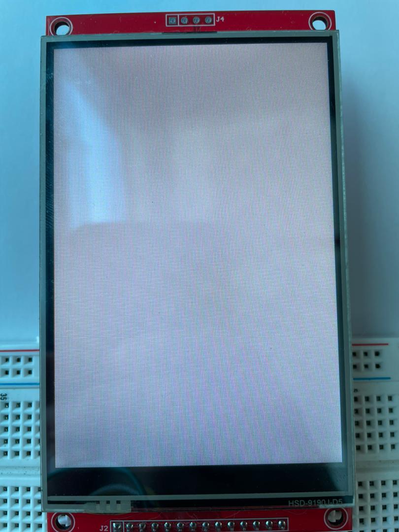
With the display pipeline operational, the next step is to integrate LVGL to move from direct framebuffer writes to higher-level graphical interface rendering.
LVGL
Adding LVGL to the project
LVGL can be added from a specific upstream release, but this implementation uses the version already included in the Third Party Hardware Drivers Extension repository. Copy the lvgl folder from third_party_hw_drivers_extension/driver/thirdparty/lvgl into a local vendor directory in the project. Then, to include the LVGL source files, go to the Simplicity panel in VS Code, right-click the current project, and select “Open Configurators 2.0”.
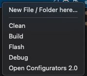
Then a new tab in the editor should open and show a menu. To include the source of lvgl click add below of “Folder Name”.
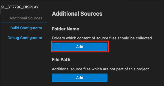
Then, the UI is going to expect you to enter the path of the folder and click the OK button.


After adding the LVGL sources, the project compiles with several compiler warning conditions that require additional GCC configuration.

The first attempt is to add the GCC flag -Wno-error=type-limits through the Build Configurator.
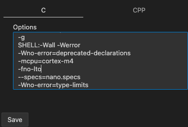
In this case, the warning configuration is not resolved through the Build Configurator alone. Removing -Werror also does not clear the build issue.
The next approach is to update target_compile_options directly in CMakeLists.txt.
target_compile_options(sl_ST7796_display PUBLIC
    # Set additional compiler flags here
    $<$<COMPILE_LANGUAGE:C>:-Wno-error=type-limits>
)
After resolving the type-limits warning condition, an additional unused-parameter warning remains and can be addressed through the same compile configuration approach.
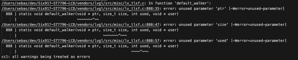
Add -Wno-error=unused-parameter to handle the remaining warning.
target_compile_options(sl_ST7796_display PUBLIC
    # Set additional compiler flags here
    $<$<COMPILE_LANGUAGE:C>:-Wno-error=type-limits>
    $<$<COMPILE_LANGUAGE:C>:-Wno-error=unused-parameter>
)
With the additional compiler flags applied, the LVGL integration compiles successfully.
The next step is to add an lv_conf.h file to the config folder using the configuration provided here, then rebuild the project before continuing with the LVGL display integration.
Integrate LVGL
LVGL initialization begins by setting up the library, draw buffer, and display driver. The display driver receives the buffer and a flush callback used to transfer framebuffer updates to the screen.
#include <lvgl.h>
...
#define DISPLAY_WIDTH 480
#define DISPLAY_HEIGHT 320
...
static lv_disp_draw_buf_t draw_buf;
static lv_disp_drv_t disp_drv;
...
void init_lvgl() {
    lv_init();
    lv_disp_draw_buf_init(&draw_buf, (lv_color_t *)framebuffer1,
  NULL, DISPLAY_WIDTH * DISPLAY_HEIGHT);
    lv_disp_drv_init(&disp_drv);

    disp_drv.hor_res = DISPLAY_WIDTH;
    disp_drv.ver_res = DISPLAY_HEIGHT;
    disp_drv.flush_cb = disp_flush;
    disp_drv.draw_buf = &draw_buf;

    lv_disp_drv_register(&disp_drv);
}
Two elements are still required: the framebuffer allocation and the disp_flush callback. The framebuffer can be placed in PSRAM, which was added earlier to provide external memory for graphical data. First, it is necessary to make sure that the PSRAM is available by initializing it.
...
#include <sl_si91x_psram.h>
#include <sl_si91x_psram_handle.h>
...
static uint16_t *framebuffer1 = (uint16_t *)PSRAM_BASE_ADDRESS;
...
sl_status_t PSRAM_init(void) {
    sl_status_t status = SL_STATUS_OK;
    status = sl_si91x_psram_uninit();
    if (status != SL_STATUS_OK)
    {
        return status;
    }
    printf("psram uninit donern");

    // Initialize PSRAM. Just to throw an error if the PSRAM is not present
    status = sl_si91x_psram_init();
    if (status != PSRAM_SUCCESS)
    {
        return status;
    }
    printf("psram init donern");
    return status;
}
The disp_flush callback receives the area to update and the pixel buffer generated by LVGL. It sets the display window, transfers the pixel data, and signals LVGL when the flush operation is complete. To support this flow, write_color is refactored into write_pixels, allowing the display write function to accept a pixel buffer and wait for the transfer to finish.
void disp_flush(lv_disp_drv_t *disp_drv, const lv_area_t *area, lv_color_t *color_p)
{
    printf("x1: %d, x2: %d, y1: %d, y2: %drn", area->x1, area->x2, area->y1, area->y2);
    uint16_t w= area->x2 - area->x1 + 1;
    uint16_t h = area->y2 - area->y1 + 1;
    ST7796_set_addr_window(area->x1, area->y1, w, h);
    write_pixels((uint16_t *)color_p, w * h);
    lv_disp_flush_ready(disp_drv);
}

static volatile uint8_t block_write_pixels = 0;
void write_pixels_transfer_complete_callback(void)
{
    block_write_pixels = false;
}

sl_status_t write_pixels(uint16_t *color, uint32_t len)
{
    uint32_t i, n, size;
    sl_status_t status;

    if (!len)
    {
        return SL_STATUS_INVALID_PARAMETER;
    }
    for (n = 0; n < len; n += MAX_FRAMEBUFFER_PIXEL_COUNT)
    {
        while (block_write_pixels);
        if (n + MAX_FRAMEBUFFER_PIXEL_COUNT <= len)
        {
            size = MAX_FRAMEBUFFER_PIXEL_COUNT;
        }
        else
        {
            size = len - n;
        }

        for (i = 0; i < size; i++)
        {
            dma_buffer[i] = (*color) >> 8 | ((uint16_t)((*color) & 0xff) << 8);
            color++;
        }
        block_write_pixels = true;
        status = write_display(dma_buffer,
                               size * 2,
                               write_pixels_transfer_complete_callback);
        if (SL_STATUS_OK != status)
        {
            block_write_pixels = false;
            goto error;
        }
    }

    while (block_write_pixels);
    return SL_STATUS_OK;
error:
    return SL_STATUS_IO;
}
The following function creates basic LVGL labels to verify that the graphics stack is rendering UI elements.
void draw_hello_world(void)
{
    lv_obj_t * label1 = lv_label_create(lv_scr_act());
    lv_label_set_long_mode(label1, LV_LABEL_LONG_WRAP);     /*Break the long lines*/
    lv_label_set_recolor(label1, true);                      /*Enable re-coloring by commands in the text*/
    lv_label_set_text(label1, "#0000ff Re-color# #ff00ff words# #ff0000 of a# label, align the lines to the center "
                      "and wrap long text automatically.");
    lv_obj_set_width(label1, 150);  /*Set smaller width to make the lines wrap*/
    lv_obj_set_style_text_align(label1, LV_TEXT_ALIGN_CENTER, 0);
    lv_obj_align(label1, LV_ALIGN_CENTER, 0, -40);

    lv_obj_t * label2 = lv_label_create(lv_scr_act());
    lv_label_set_long_mode(label2, LV_LABEL_LONG_SCROLL_CIRCULAR);     /*Circular scroll*/
    lv_obj_set_width(label2, 150);
    lv_label_set_text(label2, "It is a circularly scrolling text. ");
    lv_obj_align(label2, LV_ALIGN_CENTER, 0, 40);
}
The initialization sequence now combines PSRAM setup, MIPI DBI initialization, ST7796S startup, LVGL initialization, and the sample UI drawing routine.
 void app_init(void)
{
    sl_status_t status = SL_STATUS_OK;
    if (PSRAM_init() != SL_STATUS_OK)
    {
        printf("PSRAM_init failed 0x%02lXrn", status);
        return;
    }

    // init MIPI driver
    status = mipi_dbi_device_init(&mipi_dbi_device, (const struct mipi_dbi_config *)&mipi_config);
    if (status != SL_STATUS_OK)
    {
        printf("mipi_dbi_device_init 0x%02lXrn", status);
        return;
    }
    printf("mipi dbi device init donern");

    if (ST7796_init() != SL_STATUS_OK)
    {
        printf("ST7796_init failed 0x%02lXrn", status);
        return;
    }

    init_lvgl();

    draw_hello_world();
}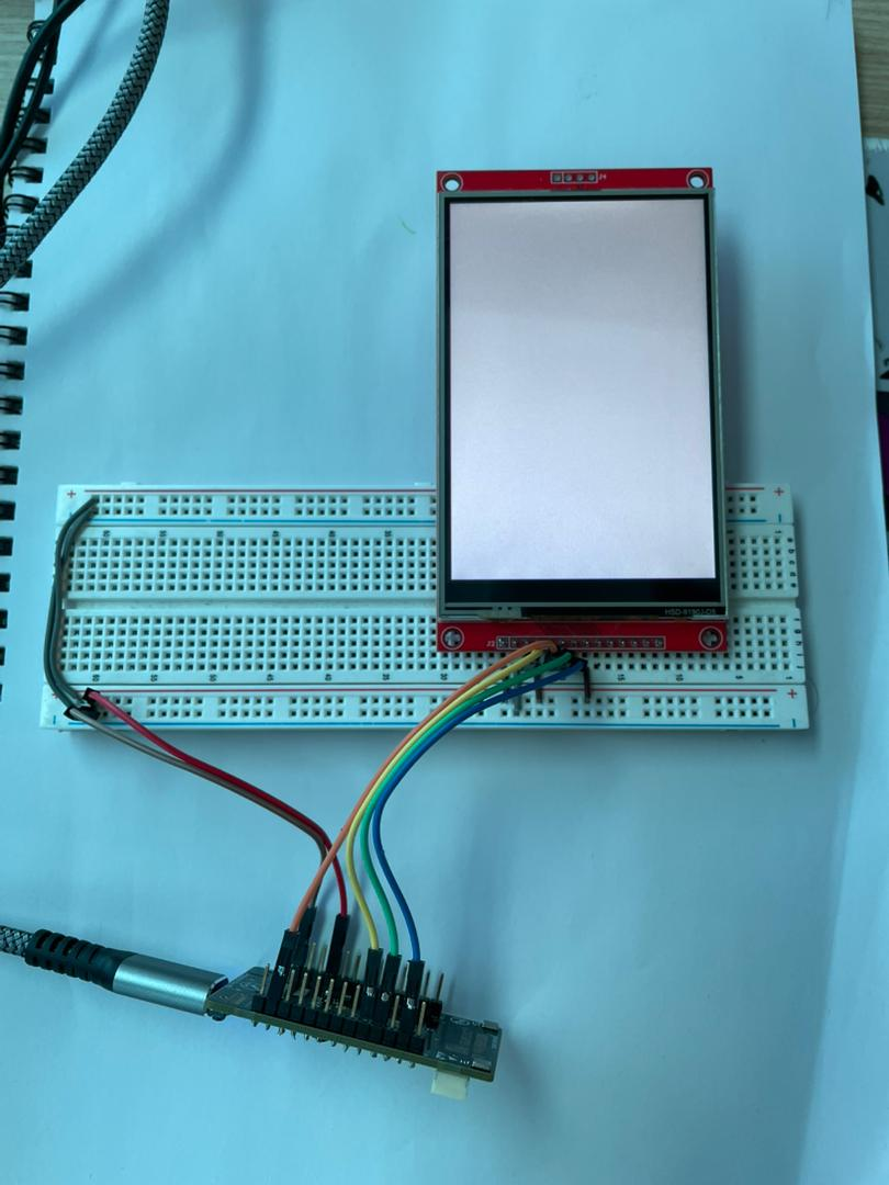
At this stage, the display remains inactive because LVGL still requires a periodic timing loop to process rendering updates and internal events.
static sl_sleeptimer_timer_handle_t lvgl_tick_timer;

void app_init(void)
{
 sl_sleeptimer_start_periodic_timer_ms(&lvgl_tick_timer,
                                      LVGL_TIMER_PERIOD,
                                      lvgl_tick_timer_callback,
                                      NULL,
                                      0,
                                      0);
  ...
}

void app_process_action(void)
{
    lv_timer_handler_run_in_period(5);
}


void lvgl_tick_timer_callback(sl_sleeptimer_timer_handle_t *timer,
                              void *data)
{
    (void)timer;
    (void)data;

    lv_tick_inc(LVGL_TIMER_PERIOD);
}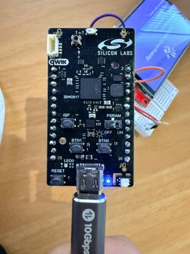
The implementation is now complete, with the display connected, initialized, and rendering an LVGL-based interface.
GitHub Repository https://github.com/krasamo/Six917-ST7796-LCD
Engineering Takeaways
This implementation demonstrates how the Silicon Labs SiWx917 can support embedded graphical interfaces using GSPI, DMA-assisted transfers, external PSRAM framebuffers, and LVGL rendering. Beyond basic display bring-up, the project highlights the coordination required between peripheral configuration, memory management, rendering pipelines, and graphics frameworks when building connected embedded products with local user interfaces.
The reference architecture can serve as a starting point for IoT products that require status displays, device interaction, local telemetry visualization, or lightweight graphical dashboards running directly on embedded hardware.